

The 5 Most Important Aspects of External Protection Against the Effects of Lightning
Lightning Risk Analysis
The lightning risk analysis takes into account many factors. This article will shed light on one of the factors: the protection of structures and its five most important aspects: lightning rod, electro-geometric model, capturing surface areas, down conductors and, of course, grounding system.
The protection of electrical or electronic facilities and equipment is not considered here, only the most important aspects of external protection of structures:
1. Protection Systems (Lightning Rods)
The purpose of these is to protect the structures against direct rays. By catching lightning and running the ground discharge current, they avoid
Damage related to the lightning itself and associated current flow.
Lightning rods are divided into three categories:
1.1 Single Spike Air Terminal
The Single spike air terminal creates a vital role in the lightning protection system. This device shall be installed at the disclosed points and the corners of the building. JMV fabricates this single spike air terminal that catches the lightning strike further connected with the down conductor through which the current dissipates into the earth. We offer this air terminal in several materials such as aluminum, copper coated aluminum and copper clad steel.
Eliminate the Risk Through Easy Installation
JMV manufactures the single spike air terminal which is available as chambered type self- supporting with different type of base support that eradicate the hazardous effect generated through the lightning strike. The product is tested as per IEC 62561-2 standard.
1.2 Mesh Cage Lightning Rod
The mesh cage consists of a network of conductors arranged around the exterior of the building so that its entire volume is circumscribed. Bus bars (0.3 to 0.5 m high) are added to this network at regular intervals at salient points (roofs, gutters, etc.).
All conductors are interconnected to the grounding system (foundation) by down conductors.

1.3 Earthed Lightning Rod
This system is used over certain buildings, outdoor storage areas, power lines (overhead ground wire), etc. The electro geometric model of the sphere is applied to these.

Since the installation of lightning rods considerably increases the risk of overvoltage’s, surge protectors should also be used. According to the IEC 60364 standard, a class I surge protector (min. Imp 12.5 kA - 10/350 waveform) is required at the source of the installation.
This value can be specified by a risk analysis if necessary (IEC 62305 or similar).
2. The Electro Geometric Model
The choice and placement of lightning capture devices requires a specific study of each site, in order to ensure that the lighting will preferably "fall" on one of the predefined points (lightning rods) and not on any other part of the building.
There are several methods to do this, depending on the type of capture device (lightning rod) and national work practices (see IEC 62305).
One of them, called the "electro geometric model" method (or imaginary sphere model), defines the spherical volume theoretically protected by a lightning rod according to the intensity of the discharge current of the first arc.
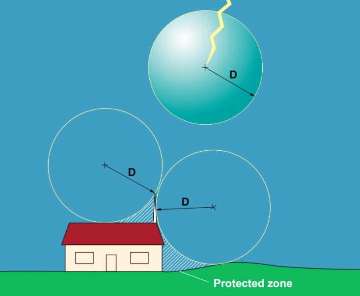
Figure 3 - General principle of the electrogeometric model
The higher this current, the greater the probability of capture and the larger the protected area.
The theoretical radius (D) of the sphere is defined by the relationship: D = 10 × I2 / 3, where D is in meters and I is in kA.
Table 1 - Theoretical radius (D) of the sphere and lightning current values
D (m) | 15 | 29 | 46 | 96 | 135 | 215 |
I (kA) | 2 | 5 | 10 | 30 | 50 | 100 |
For optimal protection incorporating the lowest probable lightning current values (protection level I), a 20 m sphere (I = 2.8 kA) should be considered.
Protection Levels (IEC 62305)
The model must be adapted according to the type of protection device (monopastane lightning rod, mesh cage, earth cables) and the structure to be protected.
The IEC 62305 standard defines protection volumes according to four protection levels based on the probability of capture:
Table 2 - Protection volumes according to four protection levels
Level | I | II | II | IV |
Probability of capture (%) | 99 | 97 | 91 | 84 |
Min. capture current (kA) | 3 | 5 | 10 | 16 |
Max. spark over distance (m) | 20 | 30 | 45 | 60 |
3. Capture Surface Areas
When the site to be protected consists of several buildings or extends beyond the reach of a single capture device (lightning rod), a protection plan for the area must be drawn up, juxtaposing the different theoretical capture surfaces.
It is always difficult to achieve full coverage of a site when it is made up of structures of different heights.
The superposition of the protection plane on the layout of the area allows you to see uncovered areas, but above all it should help to consider in depth taking into account:
The probability of lightning striking by determining the main points of impact (towers, chimneys, antennas, light poles, masts, etc.)
The sensitivity of the equipment housed in the buildings (communication and computer equipment, PLC, etc.)
The potential risk associated with the business or the types of material stored (fire, explosion, etc.)
There are two ways to protect these links:
WAY # 1 - Shielding or use of Faraday cages that, in addition to protecting against these fields, will mainly maintain the equipotentiality of the link (adjacent ground conductor, torsion, conductor shield, etc.)
WAY # 2 - Galvanic decoupling, which will electrically separate buildings (opt couplers, fiber optics, isolation transformers, etc.).
The protection plan must take into account the buildings and structures to be protected against direct lightning strikes, but must also take into account the elements or inbuilt areas for which lightning can cause destructive effects.

Figure 4 - Example of a protection plan
In this (imaginary) site we can see that the sensitive areas: manufacturing, storage, processing, etc., have been effectively protected by lightning rods or by a mesh cage, but that two areas are not protected, as they are considered low. -Risk: reception area and parking.
A further consideration shows that the light poles that illuminate the parking lot could be struck by lightning and transmit the lightning to the facility, and that the reception area that houses the telephone switchboard and the public address (beep) antenna represents an area that is both vulnerable and sensitive.
The pump station is theoretically protected by the silo lightning rods that are much taller. A situation that, however, should not allow us to forget that in this case a lateral beam is possible.
4. Down - Conductor
These provide the link between the lightning rod itself (rod, cage, wire) and the ground electrode. They are subjected to strong currents and, therefore, must have a suitable section (minimum 50 mm2 of copper), flat (HF current), firmly fixed and follow the shortest possible path.
They should not have rises or sharp angles. The conductors can be equipped with electric shock counters.
The consequences in the installation of the effects caused by the circulation of the lightning current in the down conductors can be minimized by:
- Increase the number of down conductors to divide the current and limit the effects caused.
- Make sure down conductors are interconnected with bonding systems on all floors of the building.
- Creation of potential compensation systems that incorporate all conductive elements, including inaccessible ones:
- Fluid tubes,
- Protection circuits,
- Reinforcements in concrete,
- Metal frames, etc.
- Avoid placing down-conductors near sensitive areas or equipment (computers, telecommunications, etc.).

Figure 5 - Interconnection of down conductors with bonding systems in buildings
In multi-story buildings, it is recommended that the arrester down conductors be connected to the bonding systems on each floor.
If this is not done, the difference in voltage that occurs between the down conductors and the internal exposed conductive parts could cause a spark through the walls of the building.
In fact, the flow of high frequency lightning current can cause a significant voltage increase in the down conductor (several hundred kV) due to the increase in its high frequency impedance.
5. Grounding System
This is an essential element in lightning protection: all exposed conductive parts, which in turn are interconnected, must be connected and the system must be able to discharge the lightning current, avoiding a voltage surge in the system itself. grounding and the surrounding earth. .
Although it must be low enough (<10 Ω), the low frequency resistance value of the grounding electrode is less important than its shape and size when it comes to discharge of the high frequency lightning current.
